Ref: https://payloadcms.com/docs/getting-started/installation
Check current node version
[codesyntax lang=”bash”]
|
1 2 |
satria@teddy:~$ node -v v16.15.1 |
[/codesyntax]
Use node version 20.9.0+
Check available node version
[codesyntax lang=”bash”]
|
1 2 3 4 5 6 7 8 9 10 11 12 13 14 15 16 |
satria@teddy:~$ nvm alias default -> 18.18.2 (-> v18.18.2) iojs -> N/A (default) unstable -> N/A (default) node -> stable (-> v20.15.1) (default) stable -> 20.15 (-> v20.15.1) (default) lts/* -> lts/iron (-> N/A) lts/argon -> v4.9.1 (-> N/A) lts/boron -> v6.17.1 (-> N/A) lts/carbon -> v8.17.0 (-> N/A) lts/dubnium -> v10.24.1 (-> N/A) lts/erbium -> v12.22.12 (-> N/A) lts/fermium -> v14.21.3 (-> N/A) lts/gallium -> v16.20.2 (-> N/A) lts/hydrogen -> v18.20.4 lts/iron -> v20.18.0 (-> N/A) |
[/codesyntax]
So use node stable 20.15.1
[codesyntax lang=”bash”]
|
1 2 3 4 |
satria@teddy:~$ nvm use stable Now using node v20.15.1 (npm v10.7.0) satria@teddy:~$ node -v v20.15.1 |
[/codesyntax]
Create a new dir ‘PayloadCMS’
[codesyntax lang=”bash”]
|
1 2 3 |
satria@teddy:~$ cd Documents/projects/ satria@teddy:~/Documents/projects$ mkdir payloadcms satria@teddy:~/Documents/projects$ cd payloadcms/ |
[/codesyntax]
Install the Payload CMS (blank)
[codesyntax lang=”bash”]
|
1 2 3 4 5 6 7 8 9 10 11 12 13 14 15 16 17 18 19 20 21 22 23 24 25 26 27 28 29 30 31 32 33 34 35 36 37 38 39 40 41 42 43 44 45 46 47 48 49 50 51 52 53 54 55 56 57 58 59 60 61 62 63 64 |
satria@teddy:~/Documents/projects/payloadcms$ npx create-payload-app Need to install the following packages: create-payload-app@3.11.0 Ok to proceed? (y) ┌ create-payload-app │ ◇ ────────────────────────────────────────────╮ │ │ │ Welcome to Payload. Let's create a project! │ │ │ ├───────────────────────────────────────────────╯ │ ◇ Project name? │ PayloadTest │ ◇ Choose project template │ blank │ ◇ Select a database │ MongoDB │ ◇ Enter MongoDB connection string │ mongodb://127.0.0.1/payload-test │ │ ◇ Using npm. │ ◇ Successfully installed Payload and dependencies │ ▲ ? Failed to initialize git repository. │ ◇ [DEBUG] .env.example file successfully updated │ ◇ [DEBUG] .env file successfully created or updated │ ◇ Payload project successfully created! │ ◇ Next Steps ──────────────────────────────────────╮ │ │ │ │ │ Launch Application: │ │ │ │ - cd ./payload-test │ │ - npm run dev or follow directions in README.md │ │ │ │ Documentation: │ │ │ │ - Getting Started │ │ - Configuration │ │ │ │ │ │ │ ├─────────────────────────────────────────────────────╯ │ └ Have feedback? Visit us on GitHub. npm notice npm notice New major version of npm available! 10.7.0 -> 11.0.0 npm notice Changelog: https://github.com/npm/cli/releases/tag/v11.0.0 npm notice To update run: npm install -g npm@11.0.0 npm notice |
[/codesyntax]
Launch the App
[codesyntax lang=”bash”]
|
1 2 3 4 5 6 7 8 9 10 11 12 13 14 15 |
satria@teddy:~/Documents/projects/payloadcms$ cd ./payload-test/ satria@teddy:~/Documents/projects/payloadcms/payload-test$ npm run dev > payload-test@1.0.0 dev > cross-env NODE_OPTIONS=--no-deprecation next dev ▲ Next.js 15.1.0 - Local: http://localhost:3000 - Network: http://192.168.1.23:3000 - Environments: .env - Experiments (use with caution): · turbo ✓ Starting... ✓ Ready in 1654ms |
[/codesyntax]
Open it on the browser: http://localhost:3000/
Because it’s blank, so it’ll display a message
404
This page could not be found.
Go to the admin page http://localhost:3000/admin
Note: Make sure the mongod service is already started. If not, pls start it
[codesyntax lang=”bash”]
|
1 2 3 4 5 6 7 8 9 10 11 12 13 14 15 |
sudo service mongod start sudo service mongod status ● mongod.service - MongoDB Database Server Loaded: loaded (/lib/systemd/system/mongod.service; disabled; vendor prese> Active: active (running) since Fri 2024-12-27 16:52:47 WIB; 2s ago Docs: https://docs.mongodb.org/manual Main PID: 33822 (mongod) Memory: 202.2M CPU: 759ms CGroup: /system.slice/mongod.service └─33822 /usr/bin/mongod --config /etc/mongod.conf Des 27 16:52:47 teddy systemd[1]: Started MongoDB Database Server. Des 27 16:52:47 teddy mongod[33822]: {"t":{"$date":"2024-12-27T09:52:47.606Z"}, |
[/codesyntax]
For the first/empty user, it’ll be redirected to http://localhost:3000/admin/create-first-user
with this form
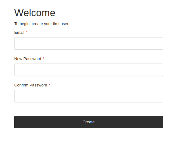
So fill the form with your user.
for example:
email: advcha@yahoo.com
password: Admin@123
So the admin dashboard will be like this
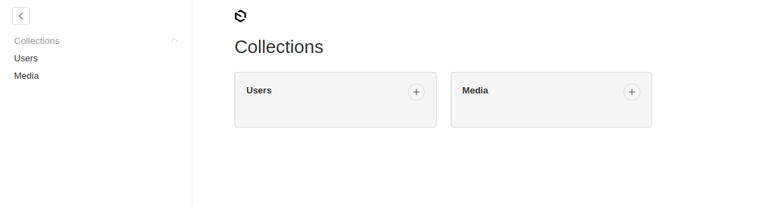
You can add any new user and media
The Code
The config in src/payload.config.ts
Add Payload Visual Editor –> DO THIS ON THE PAYLOAD WEB TEMPLATE
Ref: https://www.npmjs.com/package/payload-visual-editor
Payload Web Template
The same steps:
[codesyntax lang=”bash”]
|
1 2 3 4 5 6 7 8 9 10 11 12 13 14 15 16 17 18 19 20 21 22 23 24 25 26 27 28 29 30 31 32 33 34 35 36 37 38 39 40 41 42 43 44 45 46 47 48 49 50 51 52 53 54 |
satria@teddy:~/Documents/projects/payloadcms$ npx create-payload-app ┌ create-payload-app │ ◇ ────────────────────────────────────────────╮ │ │ │ Welcome to Payload. Let's create a project! │ │ │ ├───────────────────────────────────────────────╯ │ ◇ Project name? │ PayloadWeb │ ◇ Choose project template │ website │ ◇ Select a database │ MongoDB │ ◇ Enter MongoDB connection string │ mongodb://127.0.0.1/payload-web │ │ ◇ Using npm. │ ◇ Successfully installed Payload and dependencies │ ▲ ? Failed to initialize git repository. │ ◇ [DEBUG] .env.example file successfully updated │ ◇ [DEBUG] .env file successfully created or updated │ ◇ Payload project successfully created! │ ◇ Next Steps ──────────────────────────────────────╮ │ │ │ │ │ Launch Application: │ │ │ │ - cd ./payload-web │ │ - npm run dev or follow directions in README.md │ │ │ │ Documentation: │ │ │ │ - Getting Started │ │ - Configuration │ │ │ │ │ │ │ ├─────────────────────────────────────────────────────╯ │ └ Have feedback? Visit us on GitHub. |
[/codesyntax]
Go to the dir ‘payload-web’ then run!
[codesyntax lang=”bash”]
|
1 2 3 4 5 6 7 8 9 10 11 12 13 14 15 |
satria@teddy:~/Documents/projects/payloadcms$ cd payload-web/ satria@teddy:~/Documents/projects/payloadcms/payload-web$ npm run dev > payload-web@1.0.0 dev > cross-env NODE_OPTIONS=--no-deprecation next dev ▲ Next.js 15.1.3 - Local: http://localhost:3000 - Network: http://192.168.1.23:3000 - Environments: .env - Experiments (use with caution): · turbo ✓ Starting... ✓ Ready in 1679ms |
[/codesyntax]
Open it in your browser: http://localhost:3000
The admin : http://localhost:3000/admin
For the first/empty user, it’ll be redirected to http://localhost:3000/admin/create-first-user
So fill the form with your user.
for example:
email: advcha@yahoo.com
password: Admin@123
Name: Admin
So it’ll be like this
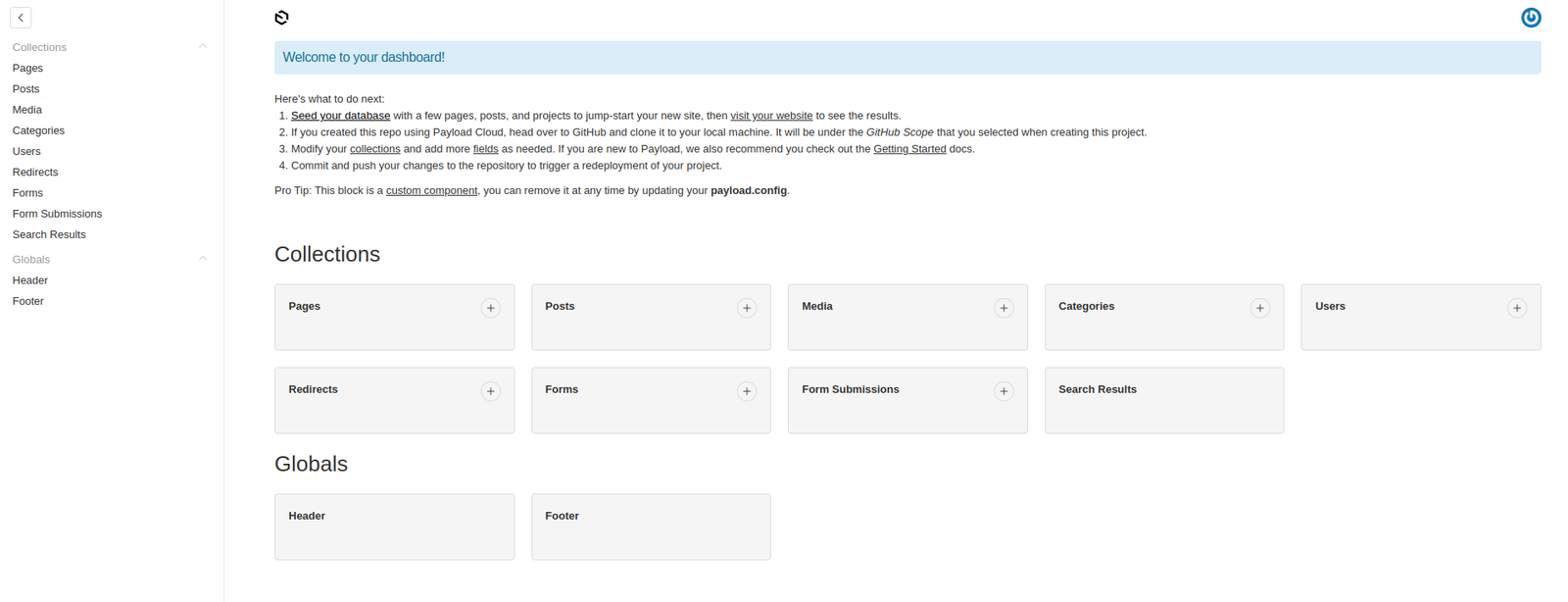
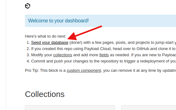
We can generate the example content by clicking ‘Seed your database’ –> ONLY ONCE
on the admin dashboard http://localhost:3000/admin
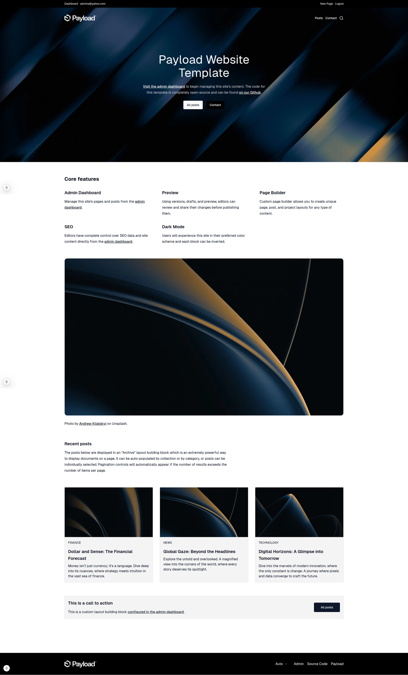
So the homepage will be like this
Add Payload Visual Editor
Ref: https://www.npmjs.com/package/payload-visual-editor
Install
[codesyntax lang=”bash”]
|
1 2 3 4 5 6 7 8 9 10 11 12 13 |
satria@teddy:~/Documents/projects/payloadcms/payload-web$ npm i payload-visual-editor added 5 packages, and audited 962 packages in 5s 247 packages are looking for funding run `npm fund` for details 3 vulnerabilities (2 moderate, 1 high) Some issues need review, and may require choosing a different dependency. Run `npm audit` for details. |
[/codesyntax]
then modify the plugin config (NOT IN src/payload.config.ts BECAUSE IT’S ALREADY LINKED TO src/plugins/index.ts
like this:
[codesyntax lang=”javascript”]
|
1 2 3 4 5 6 7 8 9 10 11 12 13 14 15 16 17 18 19 20 21 22 23 24 25 |
... / import plugin import { visualEditor } from 'payload-visual-editor' // import styles import 'payload-visual-editor/dist/styles.scss' ... export const plugins: Plugin[] = [ ... payloadCloudPlugin(), visualEditor({ previewUrl: () => `http://localhost:3000/pages/preview`, previewWidthInPercentage: 60, collections: { [COLLECTION_SLUG]: { previewUrl: () => `...`, // optional individual preview url for each collection }, }, globals: { [GLOBAL_SLUG]: { previewUrl: () => `...`, // optional individual preview url for each global }, }, }), ] |
[/codesyntax]
But when I opened http://localhost:3000/admin, it showed this error
Failed to compile
[codesyntax lang=”text”]
|
1 2 3 4 5 6 7 8 9 10 11 12 13 14 15 16 17 18 19 20 |
./node_modules/payload-visual-editor/dist/components/dropdown/index.js:30:1 Module not found: Package path ./dist/admin/components/icons/Chevron is not exported from package /home/satria/Documents/projects/payloadcms/payload-web/node_modules/payload (see exports field in /home/satria/Documents/projects/payloadcms/payload-web/node_modules/payload/package.json) 28 | Object.defineProperty(exports, "__esModule", { value: true }); 29 | exports.Dropdown = void 0; > 30 | const Chevron_1 = __importDefault(require("payload/dist/admin/components/icons/Chevron")); | ^ 31 | const react_1 = __importStar(require("react")); 32 | const Dropdown = (props) => { 33 | const [expanded, setExpanded] = (0, react_1.useState)(false); https://nextjs.org/docs/messages/module-not-found Import trace for requested module: ./node_modules/payload-visual-editor/dist/components/preview/iframe/index.js ./node_modules/payload-visual-editor/dist/components/preview/index.js ./node_modules/payload-visual-editor/dist/components/visualEditorView/index.js ./node_modules/payload-visual-editor/dist/index.js ./src/plugins/index.ts ./src/payload.config.ts ./src/app/(frontend)/[slug]/page.tsx |
[/codesyntax]
it seems visual editor can’t work with payload cms version 3.x
INSTALL Payload CMS version 2
Ref: https://payloadcms.com/docs/v2/getting-started/installation
To find out the payload cms package for npx, pls see https://www.npmjs.com/package/create-payload-app?activeTab=versions
actually there is no the package written for 2.x but there is a another package not 3.x. it’s 1.1.0. So use this
[codesyntax lang=”bash”]
|
1 2 3 4 5 6 7 8 9 10 11 12 13 14 15 16 17 18 19 20 21 22 23 24 25 26 27 28 |
satria@teddy:~/Documents/projects/payloadcms$ npx create-payload-app@1.1.0 Need to install the following packages: create-payload-app@1.1.0 Ok to proceed? (y) y Welcome to Payload. Let's create a project! ✔ Project name? … PayloadWeb2 ✔ Choose project template › website ✔ Select a database › MongoDB ✔ Enter MongoDB connection string … mongodb://127.0.0.1/payload-web1 Creating project in /home/satria/Documents/projects/payloadcms/payload-web2 ✔ Dependencies installed ✔ .env file created ✔ Payload project successfully created ★ Launch Application: - cd ./payload-web2 - npm run dev or follow directions in README.md ★ Documentation: - Getting Started - Configuration |
[/codesyntax]
note: this is actually payload cms version 2. you can see it in the dependencies in package.json file
[codesyntax lang=”javascript”]
|
1 2 3 |
... "payload": "^2.0.0", ... |
[/codesyntax]
then go to the dir and run!
Note: don’t forget to start mongod service if it’s not a;ready started!
sudo service mongod start
if you need pnpm instead of npm, install it like this
npm install -g pnpm
[codesyntax lang=”bash”]
|
1 2 3 4 5 6 7 8 9 10 11 12 13 14 15 16 17 18 19 20 21 22 23 |
satria@teddy:~/Documents/projects/payloadcms$ cd payload-web2/ satria@teddy:~/Documents/projects/payloadcms/payload-web2$ npm run dev > PayloadWeb2@1.0.0 dev > cross-env PAYLOAD_CONFIG_PATH=src/payload/payload.config.ts nodemon [nodemon] 2.0.22 [nodemon] to restart at any time, enter `rs` [nodemon] watching path(s): *.* [nodemon] watching extensions: ts [nodemon] starting `ts-node src/server.ts -- -I` [21:29:02] INFO (payload): Connected to MongoDB server successfully! [21:29:02] INFO (payload): Starting Payload... [21:29:03] INFO (payload): Payload Admin URL: http://localhost:3000/admin [21:29:06] INFO (payload): Starting Next.js... [21:29:06] INFO (payload): Next.js App URL: http://localhost:3000 webpack built e3740fda0762bb5561d6 in 12011ms webpack compiled successfully <w> [webpack.cache.PackFileCacheStrategy] Caching failed for pack: Error: No serializer registered for ConcatSource <w> while serializing webpack/lib/util/registerExternalSerializer.webpack-sources/ConcatSource -> Array { 2 items } -> ConcatSource ○ compiling /page ... ✓ Compiled /page in 5.5s (1111 modules) ✓ Compiled /next/revalidate/route in 1266ms (855 modules) |
[/codesyntax]
We can generate the example content by clicking ‘Seed your database’ –> ONLY ONCE
on the admin dashboard http://localhost:3000/admin
Add Payload Visual Editor
Ref: https://www.npmjs.com/package/payload-visual-editor
[codesyntax lang=”bash”]
|
1 |
satria@teddy:~/Documents/projects/payloadcms/payload-web2$ npm i payload-visual-editor |
[/codesyntax]
modify src/payload/payload.config.ts
[codesyntax lang=”javascript”]
|
1 2 3 4 5 6 7 8 9 10 11 12 13 14 15 16 17 18 19 20 21 22 23 24 25 26 27 28 29 30 31 32 33 34 35 36 37 38 39 40 |
... // import plugin import { visualEditor } from "payload-visual-editor"; // import styles import "payload-visual-editor/dist/styles.scss"; ... export default buildConfig({ ... plugins: [ ... visualEditor({ previewUrl: () => `http://localhost:3000/pages/preview`, previewWidthInPercentage: 60, /*collections: { [COLLECTION_SLUG]: { previewUrl: () => `...` // optional individual preview url for each collection }, }, globals: { [GLOBAL_SLUG]: { previewUrl: () => `...` // optional individual preview url for each global }, },*/ collections: { pages: { previewUrl: () => `http://localhost:3000/pages/preview`, // optional individual preview url for each pages collection }, posts: { previewUrl: () => `http://localhost:3000/posts/preview`, // optional individual preview url for each posts collection }, // Add more collections as needed }, }), ], }) |
[/codesyntax]
note: can’t use [COLLECTION_SLUG] and [GLOBAL_SLUG] because they are defined. So add ‘pages’ and ‘posts’ (probably ‘projects’ as well)
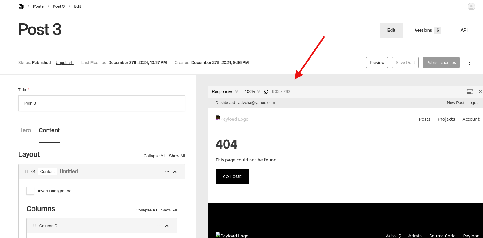
but the previewUrl() still show 404 on the admin visual editor